祝贺博士生何玉婷FeNi-NPC氧还原催化剂的研究论文被ACS Applied Materials & Interfaces接收并见刊! - 首页
Atomically Dispersed Dual-Metal ORR Catalyst with Hierarchical Porous Structure for Zn–Air Batteries

Abstract: The metal–nitrogen–carbon (M–N–C)-based catalysts are promising to replace PGM (platinum group metal) to accelerate oxygen reduction reaction due to their excellent electrocatalytic performance. However, the inferior intrinsic activity and poor active site density confining further improvement in their performance. Modulating the electronic structure and reasonably designing the pore structure are widely acknowledged effective strategies to boost the activity of the M–N–C catalysts. However, it is a great challenge to form abundant pores to regulate the electronic structure via the facile method. Herein, a hierarchical, porous dual-atom catalyst FeNi-NPC-1000 has been architectured by the Na2CO3 template method and bimetallic doping modification strategy. Benefitting from the optimized pore and electronic structure, the as-prepared FeNi-NPC-1000 possesses a high specific surface area (1412.8 m2 g–1) and improved ORR activity (E1/2 = 0.877 V vs RHE), which is superior to that of Pt/C (E1/2 = 0.867 V vs RHE). With the evidence of AC-STEM, XAS, and DFT, the FeNi-N8-C moiety is proven to be the key active site to realize high-efficiency ORR catalysis. When assembled it as an air cathode of ZABs, FeNi-NPC-1000 displays superior discharge performance (Pmax = 367.1 mW cm–2) and a stable battery long-life. This article will provide a new strategy for designing dual-metal atomic catalysts applied in metal–air batteries.
https://doi.org/10.1021/acsami.3c16216
这是何玉婷同学在博士学习阶段的第4篇research论文,博士期间一共发表了5篇高水平学术论文,为课题组做出了巨大贡献!
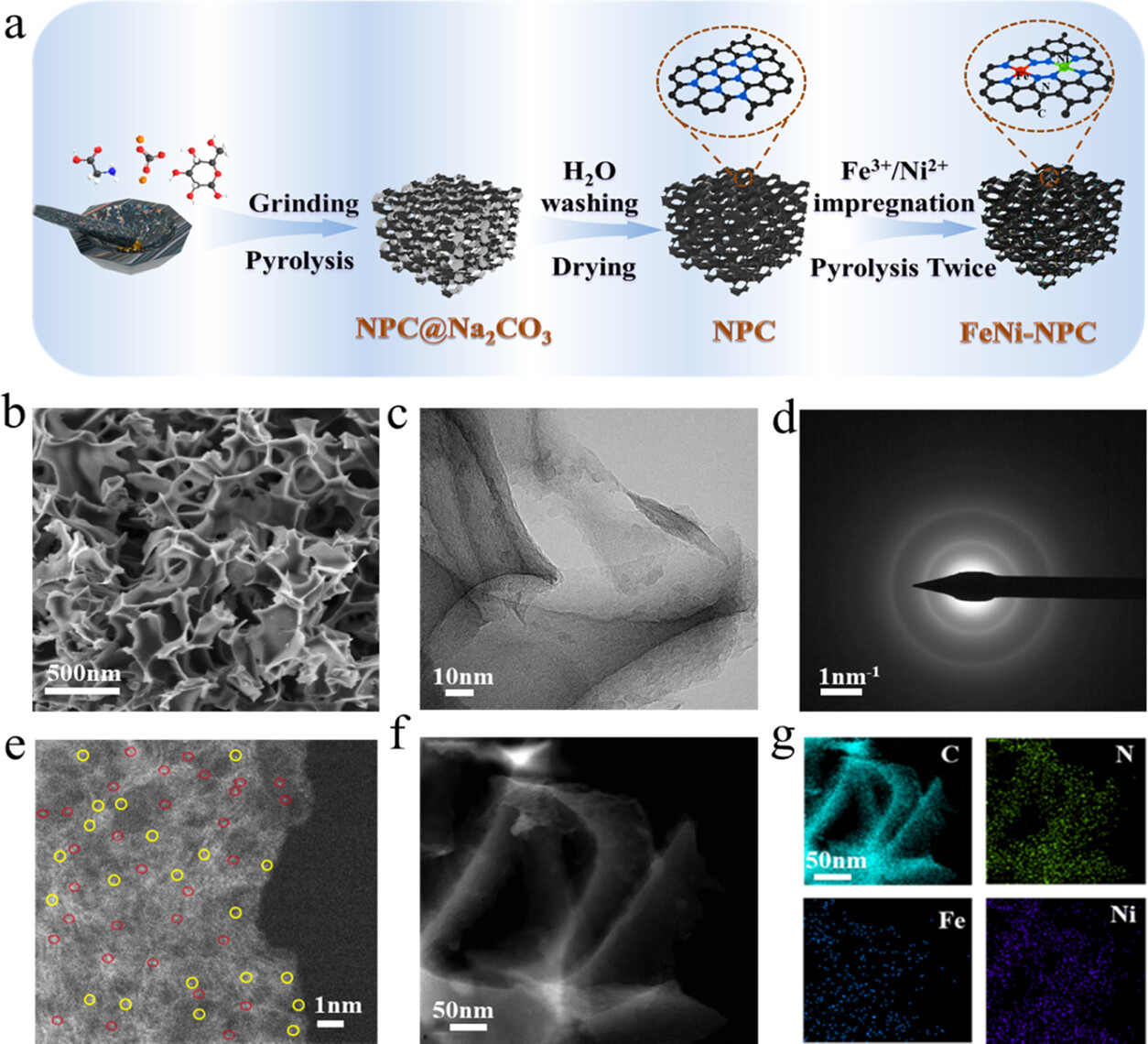
Figure 1. (a) Preparation of the FeNi-NPC catalyst. (b) SEM image of the FeNi-NPC catalyst. (c) TEM image of the FeNi-NPC catalyst. (d) Electron beam diffraction pattern image of the FeNi-NPC catalyst. (e) AC-HADDF STEM image. Bright spots represent the FeNi dual-atom site marked by red circles and Fe (Ni) single-atom site marked by yellow circles. (f–g) STEM image and elemental mappings.

Figure 2. (a) X-ray diffraction (XRD) analysis. (b) Raman spectroscopy results. (c) Nitrogen adsorption–desorption isotherms. (d) Pore size distribution of FeNi-NPC-1000, Fe-NPC-1000, and Ni-NPC-1000.

Figure 3. (a) N 1s XPS spectra of FeNi-NPC-1000, Fe-NPC-1000, and Ni-NPC-1000. (b) Fe K-edge XANES spectra of FeNi-NPC, Fe-NPC, and reference samples with enlarged pre-edge region highlighted in insets. (c) Fourier transform EXAFS spectra at the R space of FeNi-NPC, Fe-NPC, and reference materials of Fe. (d) Ni K-edge XANES spectra of FeNi-NPC, Ni-NPC, and reference samples with an enlarged pre-edge region highlighted in insets. (e) Fourier transform EXAFS spectra at the R space of FeNi-NPC, Fe-NPC, and reference materials of Ni. (f) Fitting curve of Fe EXAFS of FeNi-NPC and model 1. (g) Fitting curve of Ni EXAFS of FeNi-NPC EXAFS and model 1.

Figure 4. (a) Cyclic voltammetry curves, (b) ORR curves, and (c) Tafel slope of FeNi-NPC-1000, Fe-NPC-1000, Ni-NPC-1000, and 40 wt % Pt/C. (d) H2O2 yield and calculated electron number of FeNi-NPC-1000 and 40 wt % Pt/C. (e) i–t curves for FeNi-NPC-1000 and 40 wt % Pt/C. (f) ORR performance of FeNi-NPC-1000 before and after 100 h.

Figure 5. (a) ORR path of FeNi-N8-C and Fe-N4-C at U = 0 V. (b) ORR path of FeNi-N8-C and FeNi-N4-C at U = 1.23 V. (c) Fe 3d DOS of FeNi-N4-C. (d) Fe 3d DOS of FeNi-N8-C. (e) Total ORR process of FeNi-N8-C.
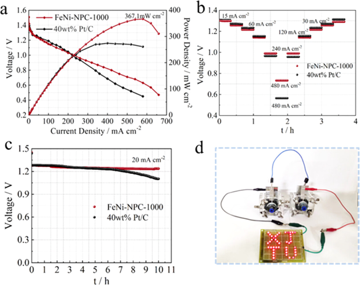
Figure 6. Performance test of ZABs assembled with FeNi-NPC-1000 and 40 wt % Pt/C. (a) Discharge curves of ZABs based on FeNi-NPC-1000 and 40 wt % Pt/C. (b) Discharge rate of ZABs with FeNi-NPC-1000 and 40% Pt/C. (c) Constant discharge curves of ZABs with FeNi-NPC-1000 and 40 wt % Pt/C. (d) The in-series ZABs assembled with FeNi-NPC-1000 lighting the “XJTU”.
-
2024
03-20
-
2024
03-11
-
2023
11-21
-
2023
10-30
-
2023
10-17
-
2023
10-17
 (创新港)
(创新港)